Your motor stutters, twitches, or sits there desync'ing like it just gave up on life. Before you blame the motor and toss the ESC, here's the 5-minute test that tells you exactly which MOSFET went up in smoke — using nothing but a multimeter in continuity mode.
Bench notes from a fellow solder-burned FPV pilot.
The Problem
The Problem Every FPV Pilot Knows
You crash. You pick the quad up. You arm it. One motor lags, stutters, or just refuses to spin smoothly. Now the eternal question kicks in:
Is it the motor, or is it the ESC?
Most people swap parts blindly, burn through spare motors, and still don't fix the problem. The truth is, 90% of the time when a single motor misbehaves and the others are fine, you've got a blown MOSFET on the ESC — and you can prove it in under five minutes.
What You Need
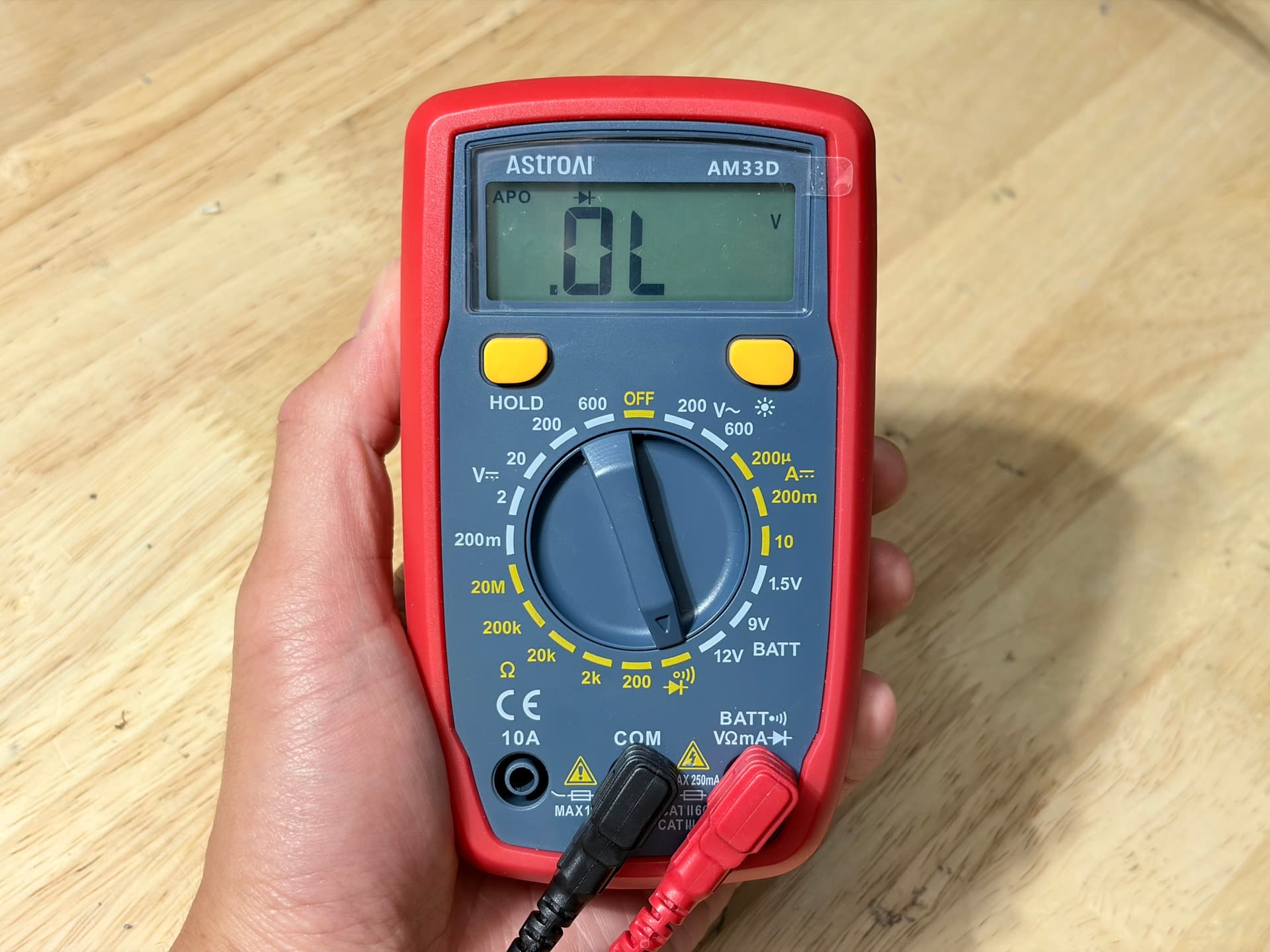
Just one tool: a multimeter set to continuity mode(the one with the diode/beep symbol). A USB microscope helps for the bonus round, but isn't required.
Quick Theory
How an ESC Drives Your Motor
Every FPV ESC has three motor phase wires — the A, B, C pads (also called the PWM pads or motor pads). Each phase is controlled by a pair of MOSFETs working as a half-bridge:
- ▸The upper (high-side) MOSFET connects the phase to battery positive (+).
- ▸The lower (low-side) MOSFET connects the phase to battery negative (−).
Three phases × two MOSFETs = six MOSFETs per ESC. If even one of them shorts or opens up, that motor phase goes wonky and the whole motor goes with it.
The beautiful part: the body diodeinside each MOSFET will leak a tiny forward voltage (around 0.4–0.8 V) when you probe it with a multimeter in continuity mode. That's our X-ray vision.
Test 1
Checking the Upper (High-Side) MOSFETs
This test reads the body diode between each motor phase and the battery positive rail.
Set your multimeter to continuity / diode mode.
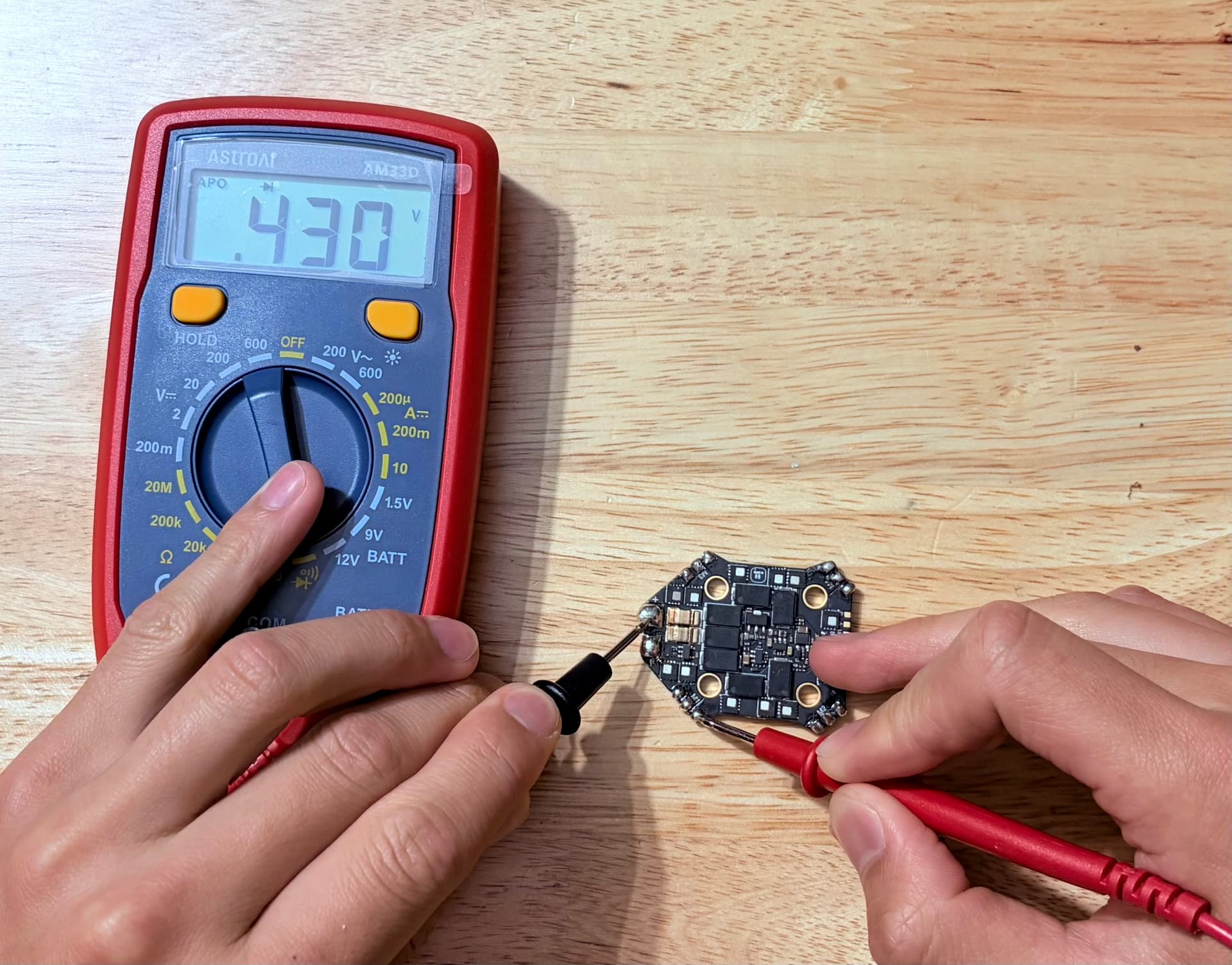
Put the BLACK (−) probe on the (+) battery pad of the ESC.
Touch the RED (+) probe to each of the three motor pads (A, B, C) one at a time.
You should see roughly the same voltage on all three pads — typically 0.4 V to 0.8 V.
The “Gotcha” Reading
If one pad shows a very different number from the other two, or the meter beeps(dead short, ~0 V) — congratulations, you just found the bad phase. The upper MOSFET on that phase is toast.
Test 2
Checking the Lower (Low-Side) MOSFETs
Same idea, flipped polarity. We're now reading the body diode between each motor phase and battery ground.
Keep the multimeter in continuity mode.
Put the RED (+) probe on the (−) battery pad of the ESC.
Touch the BLACK (−) probe to each motor pad (A, B, C).
Again — all three should read very close to each other (0.4–0.8 V). Any outlier or a continuous beep = your culprit.
Real Case Study
Spot the Damaged MOSFET
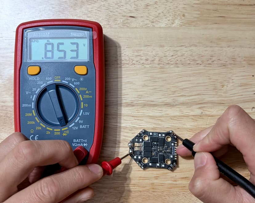
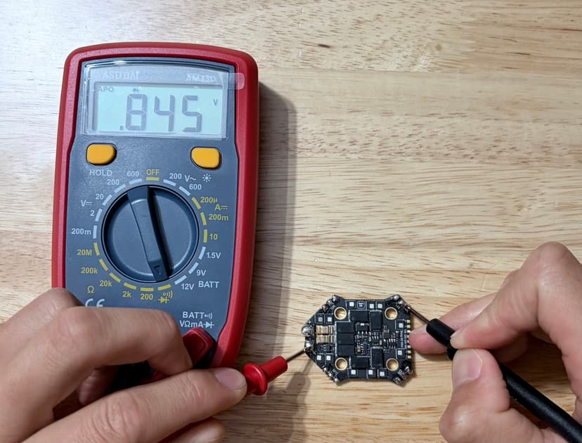
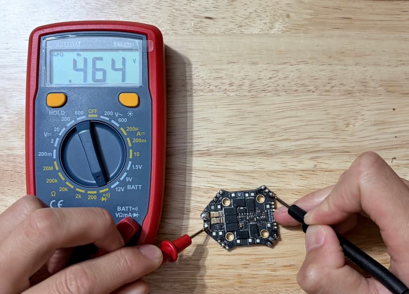
Here's an actual low-side sweep on a real ESC from the bench. Same multimeter, same setup — red probe on (−), black probe walked across phases A, B, and C. Can you pick the dead one before the reveal?
The Trap Most People Fall Into
Notice that 0.464 V is still inside the “normal” 0.4–0.8 V range. If you only checked one phase in isolation, the reading wouldn't look alarming at all. The diagnosis comes from comparing all three phases against each other. The damaged MOSFET on phase C jumps out only because its two healthy neighbors are sitting at ~0.85 V. Consistency between phases is the real test — not the absolute number.
That's it — phase C's low-side MOSFET is the one to desolder and replace. The motor on this ESC was the classic “stutter / desync on hard throttle” symptom that drove me to the bench in the first place.
Why This Works
You're not actually measuring the MOSFET channel — you're measuring the parasitic body diode that lives between drain and source on every MOSFET. A healthy diode drops 0.4–0.8 V. A shorted MOSFET drops 0 V (beep). An open MOSFET shows nothing at all.
Pinout Reference
About Those 8-Pin MOSFETs (Where the Internet Lies to You)
If you search “MOSFET pinout” online, you'll get a million pictures of TO-220 packages — the classic 3-pin Gate-Drain-Source layout used in big through-hole electronics. That is not what's on your ESC.
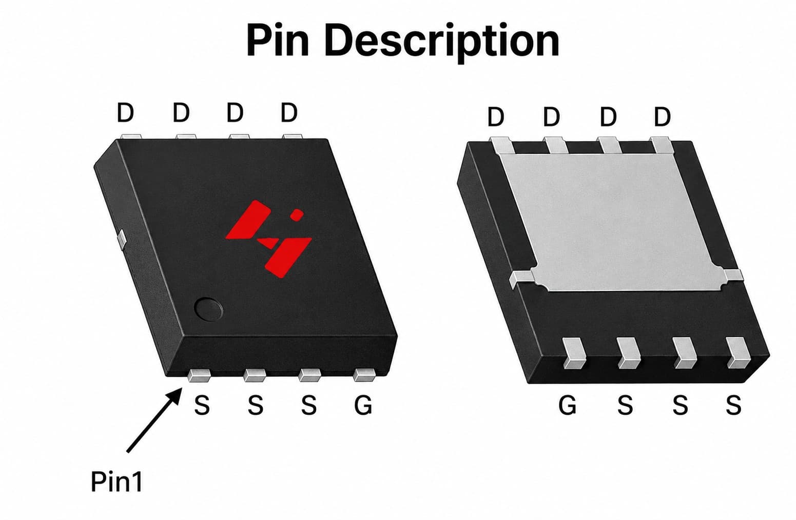
Modern FPV ESCs use tiny 8-pin SMD MOSFETs(DFN/PowerPAK style), where multiple pins are bonded together internally to handle the current. Here's the correct pinout you actually need:
TOP — all 4 pins = DRAIN
BOTTOM — 3× Source + 1× Gate (right)
- ▸Top 4 pins:
all DRAIN - ▸Bottom-left 3 pins:
all SOURCE - ▸Bottom-right pin:
GATE
Bonus Round
Pinpointing the Exact Bad MOSFET Under a Microscope
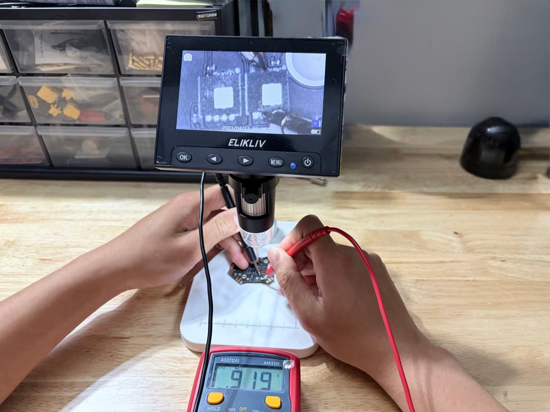
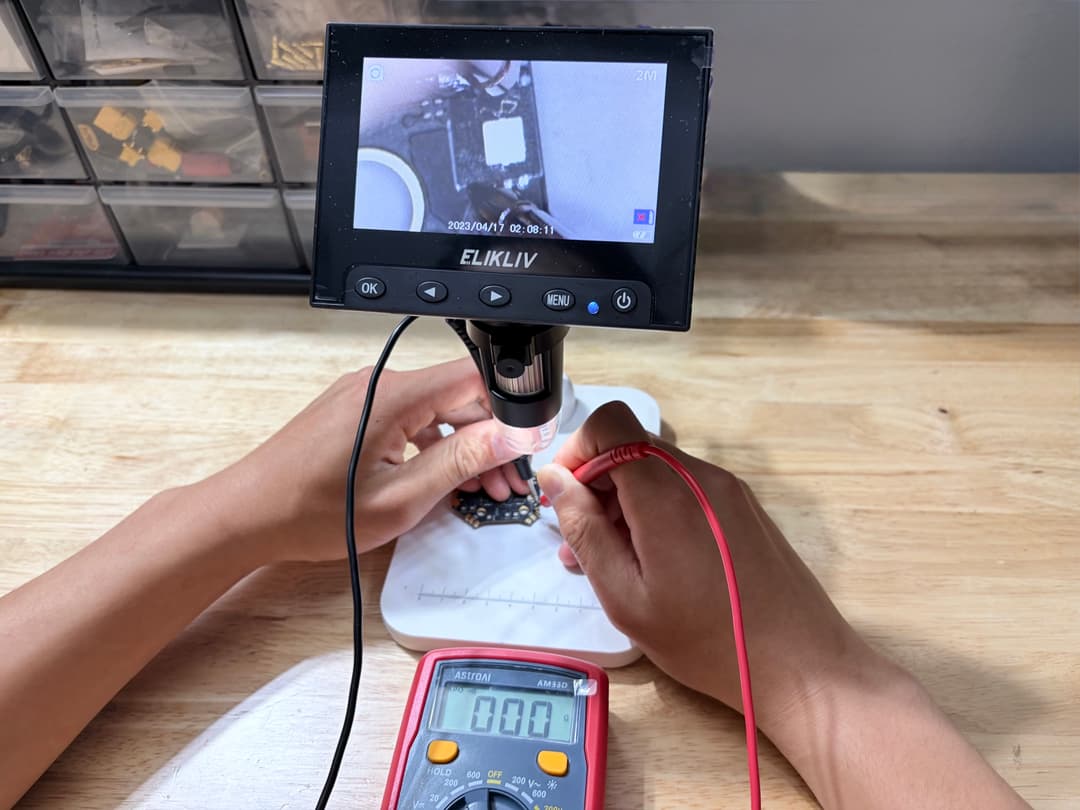
If you've already narrowed down the bad phase from Test 1 or 2, and you've got a USB microscope or even a strong loupe, you can confirm exactly which MOSFET is the problem before you reach for the hot air:
Put the BLACK (−) probe on one of the DRAIN pins (top row).
Touch the RED (+) probe to each of the three SOURCE pins (bottom row, except the rightmost).
A healthy MOSFET shows 0.4–0.8 V across the body diode. If you get an abnormal reading or a beep — you've found the devil. That's the chip to desolder.
Real Talk — This Is Fiddly
The pads are tinyand packed in tight on a typical FPV ESC. Getting both probes to land cleanly on the right pins without bridging neighbors is a bit of a balancing act. That's why the phase-level tests (Test 1 and 2) are the everyday workflow — only break out the microscope when you need to confirm which specific MOSFET in a half-bridge pair is the bad one before desoldering.
Safety Note
Never run the microscope probe-test (or any of these tests) with a battery plugged in. The probes are so close together that one slip can short a live rail and turn one bad MOSFET into several bad MOSFETs — or worse, take out the flight controller too. Bench power off. Caps discharged. Always.
Pro Tip
Don't bother probing the Gate pin during this test. Gate-to-Drain or Gate-to-Source on a healthy MOSFET should look like an open circuit; if Gate-to-Source beeps, the gate has shorted out — game over for that MOSFET regardless.
Next Steps
What To Do When You've Found It
Confirm the failure with both tests so you don't replace a perfectly good chip.
Identify the MOSFET part number printed on top of the chip (or look it up in your ESC's BOM).
Hot-air it off, clean the pads, and solder a new one back on. Watch the orientation — the gate pin is in the bottom-right corner.
Re-run both continuity tests before plugging in a battery. Confirm clean, consistent readings on all three phases.
Smoke-stopper first. Always. Don't ask me how I know.
Safety First
Never run these tests with a battery connected. Discharge any large capacitors on the ESC before probing. And if you smell that classic “blue smoke” perfume during a powered test, unplug immediately — there's usually more than one MOSFET that's about to follow its friend.
FAQ
Common Questions
Why is my FPV motor stuttering?+
Single-motor stutter on FPV drones is almost always a failed MOSFET on the ESC phase driving that motor. A shorted or open MOSFET disrupts the phase waveform, causing the motor to stutter, twitch, or desync — especially under hard throttle. The multimeter continuity test described above confirms this in under 5 minutes.
How do I know if the problem is my ESC or my motor?+
Swap the motor to a known-good ESC output. If the stutter follows the motor, replace the motor. If the stutter stays on the same output regardless of which motor you plug in, the ESC is faulty — specifically the MOSFET on that phase. The phase-level continuity tests (Test 1 and Test 2 above) will pinpoint it without any swapping.
What is motor desync in FPV drones?+
Desync happens when a motor loses track of rotor position mid-flight, usually because one of its three drive phases is delivering weak or inconsistent voltage. A blown ESC MOSFET is one of the most common root causes — the damaged chip produces an irregular phase signal that confuses the motor's timing algorithm, causing it to briefly stop and restart.
Can I repair a blown MOSFET instead of replacing the whole ESC?+
Yes. A single 8-pin SMD MOSFET costs under $2 and takes about 20 minutes to hot-air reflow. Replacing an entire ESC for one failed chip is unnecessary if you're comfortable with surface-mount soldering. Identify the part number printed on the chip, order the exact replacement, and run the continuity tests after soldering to confirm the repair before powering up.
What does a failed MOSFET read on a multimeter?+
A shorted MOSFET reads 0 V (and usually beeps in continuity mode) across drain and source. An open MOSFET reads OL (overload / infinity). A healthy MOSFET body diode reads 0.4–0.8 V. The key diagnostic is consistency: all three motor phases should read nearly identical voltages. An outlier — even one that still falls in the 0.4–0.8 V range — indicates a degraded MOSFET that should be replaced before it fails completely.
TL;DR
Final Thoughts
An ESC isn't a black box — it's just six little MOSFETs doing a synchronized dance to spin your motor. Once you can read the body diodes with a multimeter, you can diagnose 90% of “is it the motor or the ESC?” problems in five minutes flat. That's five minutes of testing instead of ordering a new ESC, waiting a week, and finding out the motor was bad anyway.
Save the spare parts for the next crash. Fly safe, solder steady.
Got a weird reading on your bench? Drop a comment with your numbers — A/B/C phase voltages on both upper and lower bridge tests — and we'll figure it out together.